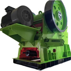
PE Jaw Crusher
The PE Jaw Crusher is mainly used for medium-size crushing of various ores and large-sized materials. It is widely applied in industries such as mining, metallurgy, building materials, highways, railways, water conservancy, and chemical engineering.
The compressive strength of the materials to be crushed should not exceed 320 MPa.
Structural Composition
1. Frame
The frame is a rigid four-wall structure with openings at the top and bottom. It is used to support the eccentric shaft and withstand the reaction force generated during crushing. Therefore, it must have sufficient strength and rigidity.
The frame is generally manufactured as an integral cast steel structure. For small-sized machines, high-quality cast iron may be used instead of cast steel. For large jaw crushers, the frame is usually cast in sections and then firmly connected into a whole using bolts, which involves a complex casting process.
For self-made small jaw crushers, the frame can also be welded from thick steel plates, though its rigidity is relatively lower.
2. Jaw Plates and Side Guard Plates
Both the fixed jaw and the movable jaw consist of a jaw body and jaw plates. The jaw plates are the main working components and are fixed to the jaw body using bolts and wedges.
The jaw body of the fixed jaw is the front wall of the frame, while the jaw body of the movable jaw is suspended on the shaft. It must have sufficient strength and rigidity to withstand the crushing reaction force, and therefore is mostly made of cast steel or cast iron.
3. Transmission Components
The eccentric shaft is the main shaft of the jaw crusher and is subjected to significant bending and torsional stresses. It is made of high-carbon steel. The eccentric portion must be precision-machined and heat-treated.
The bearing bush is cast with Babbitt alloy. One end of the eccentric shaft is equipped with a belt pulley, and the other end is fitted with a flywheel.
4. Adjustment Device
The discharge opening adjustment devices include wedge-type, shim-type, and hydraulic-type, with the wedge-type being the most commonly used.
The wedge-type adjustment consists of front and rear wedges. The front wedge can move forward and backward to support the rear toggle plate, while the rear wedge serves as the adjusting wedge and can move up and down. The inclined surfaces of the two wedges fit together, and the discharge opening size is adjusted by moving the rear wedge vertically via a screw mechanism.
For small jaw crushers, the discharge opening is adjusted by increasing or decreasing the number of shims between the rear toggle plate support and the frame.
5. Flywheel
The flywheel of the jaw crusher is used to store energy during the idle stroke of the movable jaw and release it during the crushing stroke, ensuring smooth and uniform operation of the machine. The belt pulley also functions as a flywheel.
Flywheels are generally made of cast iron or cast steel. For small machines, the flywheel is often manufactured as an integral structure. During manufacturing and installation, static balance must be carefully ensured.
6. Lubrication System
The bearings of the eccentric shaft usually adopt a centralized circulating lubrication system. The support surfaces of the eccentric shaft and toggle plate are generally lubricated with grease supplied manually using a grease gun.
Due to the small swing angle of the movable jaw, lubrication between the eccentric shaft and bearing bush is relatively difficult. Therefore, several axial oil grooves are often machined at the bottom of the bearing bush, with a circumferential oil groove in the middle to connect them. Grease is then forcibly injected using an oil pump to ensure effective lubrication.